|
Written by Robert
Dunlop
Microsoft DirectX MVP |
 |

 |
When loading a mesh from a modeling package, texture mapping
coordinates are usually included to indicate how a texture is applied to
the mesh. However, when generating our own meshes, it will often
be necessary to create texture coordinates based on the shape of the
object. One such method for generating texture coordinates
from geometry is known as spherical mapping. |
The basis of this mapping technique is to treat the object as if it were a
sphere, and mapping coordinates based by determining the position on a sphere by
angular displacement. In this article we'll take a look at two forms of
spherical mapping, one based on normals and another based on vertex position.
Spherical Mapping with Normals
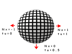
The simplest method is to use the normal of each vertex, which is usually
already pre-calculated for the purpose of lighting. Texture coordinates
are generated based on the angle of the surface at each point. Values for the texture
coordinates are calculated as follows:
As a faster alternative the following equations can be used:
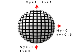
tu = Nx/2 + 0.5
tv = Ny/2 + 0.5
The result is that the coordinates are non-linear, tending to stretch the
texture around the Y and Z poles while compressing it around the X poles.
Below is an example of how to implement sphere mapping on a sphere generated
with D3DX:
struct _VERTEX
{
D3DXVECTOR3 pos; // vertex position
D3DXVECTOR3 norm; // vertex normal
float
tu; // texture
coordinates
float tv;
} VERTEX,*LPVERTEX;
#define FVF_VERTEX
D3DFVF_XYZ|D3DFVF_NORMAL|D3DFVF_TEX1
LPD3DXMESH CreateMappedSphere(LPDIRECT3DDEVICE8
pDev,float fRad,UINT slices,UINT stacks)
{
// create the sphere
LPD3DXMESH mesh;
if
(FAILED(D3DXCreateSphere(pDev,fRad,slices,stacks,&mesh,NULL)))
return NULL;
// create a copy of the mesh with
texture coordinates,
// since the D3DX function doesn't include them
LPD3DXMESH texMesh;
if
(FAILED(mesh->CloneMeshFVF(D3DXMESH_SYSTEMMEM,FVF_VERTEX,pDev,&texMesh)))
// failed, return un-textured mesh
return mesh;
// finished with the original mesh, release it
mesh->Release();
// lock the vertex buffer
LPVERTEX pVerts;
if (SUCCEEDED(texMesh->LockVertexBuffer(0,(BYTE **)
&pVerts))) {
// get vertex count
int
numVerts=texMesh->GetNumVertices();
// loop through the vertices
for (int i=0;i<numVerts;i++) {
// calculate
texture coordinates
pVerts->tu=asinf(pVerts->norm.x)/D3DX_PI+0.5f;
pVerts->tv=asinf(pVerts->norm.y)/D3DX_PI+0.5f;
// go to next
vertex
pVerts++;
}
// unlock the vertex buffer
texMesh->UnlockVertexBuffer();
}
// return pointer to caller
return texMesh;
}
Positional Spherical Mapping
|
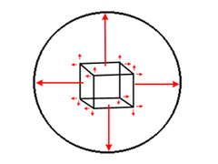 In
some cases, using normals to calculate spherical texture coordinates may not be
appropriate. For example, objects which use face normals, such as the cube
illustrated on the right, would have the same coordinates applied to each vertex
of a face. Also, regions that are relatively flat on one or more axis will
cause the texture to appear stretched. In
some cases, using normals to calculate spherical texture coordinates may not be
appropriate. For example, objects which use face normals, such as the cube
illustrated on the right, would have the same coordinates applied to each vertex
of a face. Also, regions that are relatively flat on one or more axis will
cause the texture to appear stretched.
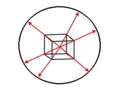
An alternative to this is to project a vector from the center of the object
outward through each vertex, and use the normalized X and Y coordinates to
calculate the texture coordinates. This has the effect of projecting each
vertex onto a theoretical sphere. An example of this technique is shown in
the following code snippet: |
// determine extents
D3DXVECTOR3 vMin,vMax;
D3DXComputeBoundingBox(pVerts,numVerts,FVF_VERTEX,&vMin,&vMax);
// calculate center
D3DXVECTOR3 vCent;
vCent=(vMax+vMin)*0.5f;
// loop through the vertices
for (i=0;i<numVerts;i++) {
// calculate normalized offset from center
D3DXVECTOR3 v;
v=pVerts->pos-vCent;
D3DXVec3Normalize(&v,&v);
// calculate texture coordinates
pVerts->tu=asinf(v.x)/D3DX_PI+0.5f;
pVerts->tv=asinf(v.y)/D3DX_PI+0.5f;
// go to next vertex
pVerts++;
}
Back to The Top